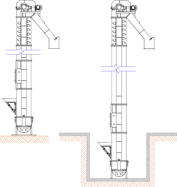
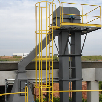
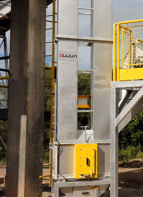
Bucket Elevator
Robust equipment, with easy access for maintenance, continuous operation, precise dosing and compact installation.
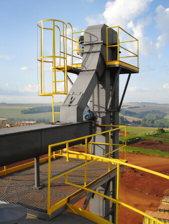
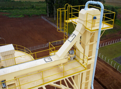
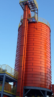
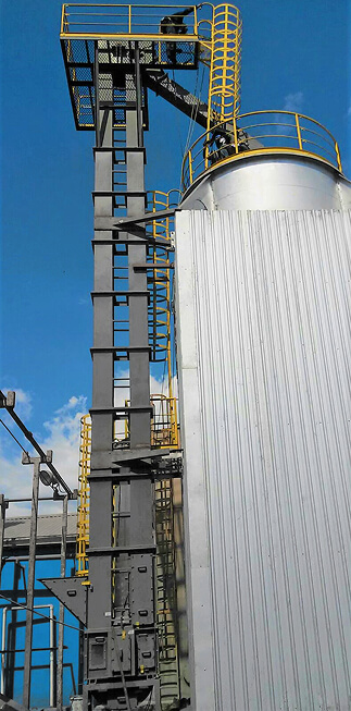
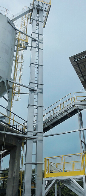
The bucket elevator is an equipment designed to convey various types of biomass. It operates vertically with subsequent discharge into the storage system.
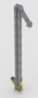
It's made of either carbon steel or stainless steel, in modules stacked on top of each other bound by flanged bolts. As it is a self-supporting equipment, no bracing is required.
The bucket elevator features a self‐cleaning system at its lower head. It is a cradle with adjustable height, which allows for greater efficiency in scraping the buckets and prevents biomass buildup inside.
Its modular design allows for application in compact projects, generally used in the feeding of vertical silos and rapid discharge silos.
Bucket Elevator (Biomass)
Used to convey biomass, such as wood chips, rice husks, sawdust, pellets, eucalyptus bark, among others.
In this elevator, the biomass is carried out by either metal or plastic buckets, which are attached to a canvas belt. The upper head features a hinged closure lid, and the driving and guided drums are supplied with a convex machining on the external diameter, which are also grooved with an internal self‐cleaning cone.
Plastic elevator buckets can be manufactured with polymers such as HDPE (High‐Density Polyethylene), PEAD EAGLE (HDPE formulation with impact and abrasion resistance), PA 6 (Nylon 6), PA 66 and PU (Premium Polyurethane). The ideal bucket material to be used depends on the type of the biomass to be lifted, therefore an appropriate biomass analisys may determine the best choice.
Technical specifications
| Models | Width (mm) | Length (mm) | Height (mm) | Power (HP) | Flow rate (m³/h) | Weight per meter (kg) |
|---|---|---|---|---|---|---|
| ECD/50 | 500 | 1.030 | 15.400 to 35.000 | 5 to 10 | 30 to 90 | 275 |
| ECD/100 | 600 | 1.030 | 15.400 to 35.000 | 7,5 to 20 | 100 to 190 | 290 |
| ECD/200 | 800 | 1.030 | 15.400 to 35.000 | 20 to 40 | 200 to 290 | 310 |
| ECD/300 | 1.000 | 1.400 | 15.400 to 35.000 | 20 to 50 | 300 to 390 | 602 |
| ECD/400 | 1.400 | 1.500 | 15.400 to 35.000 | 20 to 75 | 400 to 490 | 665 |
| ECD/600 | 1.800 | 1.900 | 15.400 to 35.000 | 20 to 100 | 500 to 650 | 790 |
The equipment can be adjusted according to your project's needs.
Bucket Elevator (Ash)
Used to convey ashes, sludges, and silicas.
In the elevator, the biomass is carried out by metal buckets fastened on a conveyor chain. The upper head features an articulating closure lid, and the driving and guided gears are induction hardened in the gear tooth area.
Technical specifications
| Models | Width (mm) | Length (mm) | Height (mm) | Power (HP) | Flow rate (m³/h) | Weight per meter (kg) |
|---|---|---|---|---|---|---|
| ECD/10 | 300 | 1.030 | 12.000 to 25.000 | 2 to 15 | 2 to 50 | 240 |
| ECD/20 | 400 | 1.030 | 12.000 to 25.000 | 3 to 30 | 10 to 100 | 275 |
The equipment can be adjusted according to your project's needs.
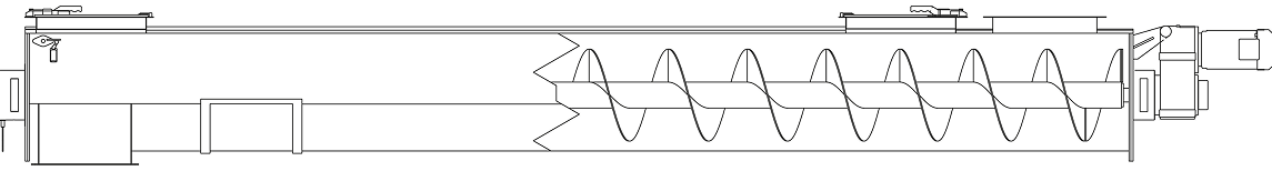
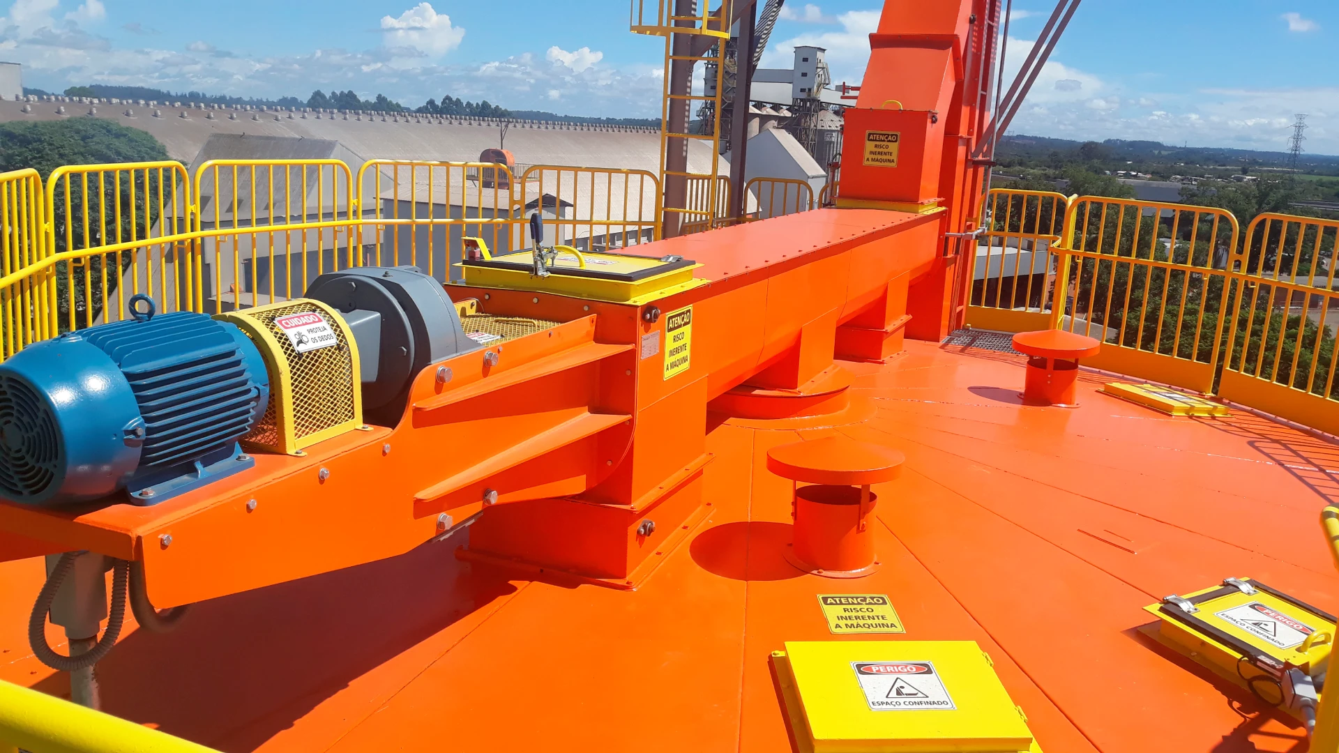
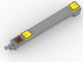
Screw Conveyor
Robust equipment with easy access for maintenance, designed for continuous operation and precise dosing.
The screw conveyor is an equipment developed for the movement and dosing of various types of biomass, either continuously or intermittently between two distinct points. The material is moved by means of helical blades.
In order to increase the equipment's lifespan, special materials can be used in its construction, such as Hardox or stainless steel screws, or even mig welding hardfacing overlays on the surfaces of the screws that come into contact with the biomass.
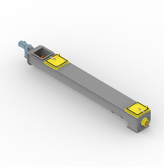
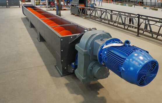
Screw Conveyor (Biomass)
Used to convey biomass, such as wood chips, rice husks, sawdust, pellets, eucalyptus bark, among others.
Depending on the technical requirements of each project, in some cases it is necessary to use intermediate bearings.
Technical specifications
| Models | RTD/300 | RTD/400 | RTD/500 | RTD/600 | RTD/700 | RTD/800 |
|---|---|---|---|---|---|---|
| Diameter (mm) | 300 | 400 | 500 | 600 | 700 | 800 |
| Length (mm) | 2.100 to 6.500 | 2.100 to 10.350 | 2.800 to 13.300 | 4.000 to 15.250 | 4.000 to 15.250 | 4.000 to 15.250 |
| Power (HP) | 4 to 7,5 | 5 to 15 | 5 to 20 | 10 to 40 | 20 to 50 | 30 to 60 |
| Flow rate (m³/h) | 4 to 30 | 30 to 80 | 80 to 200 | 200 to 300 | 300 to 400 | 400 to 500 |
| Weight (kg) | 1.400 | 2.800 | 3.600 | 5.100 | 6.200 | 7.600 |
The equipment can be adjusted according to your project's needs.
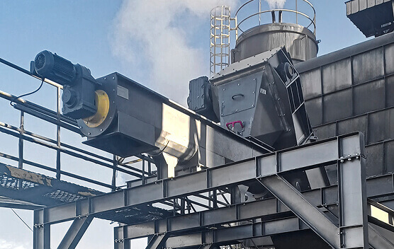
Screw Conveyor (Ash)
Used convey ashes, wet ashes, and silicas.
In some cases, it may be necessary to use special materials in the manufacturing of the bearings due to the level of abrasion of the material to be conveyed.
Technical specifications
| Models | RTD/200 | RTD/300 | RTD/400 | RTD/500 |
|---|---|---|---|---|
| Diameter (mm) | 200 | 300 | 400 | 500 |
| Length (mm) | 2.100 to 5.300 | 2.100 to 6.200 | 3.000 to 7.500 | 3.500 to 10.000 |
| Power (HP) | 2 to 5 | 3 to 6 | 5 to 7,5 | 5 to 10 |
| Flow rate (m³/h) | 1 to 4 | 2 to 6 | 5 to 15 | 15 to 30 |
| Weight (kg) | 1.000 | 1.700 | 2.300 | 3.200 |
The equipment can be adjusted according to your project's needs.
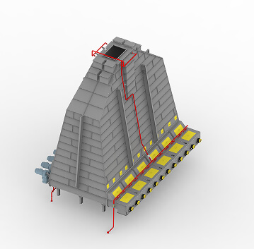
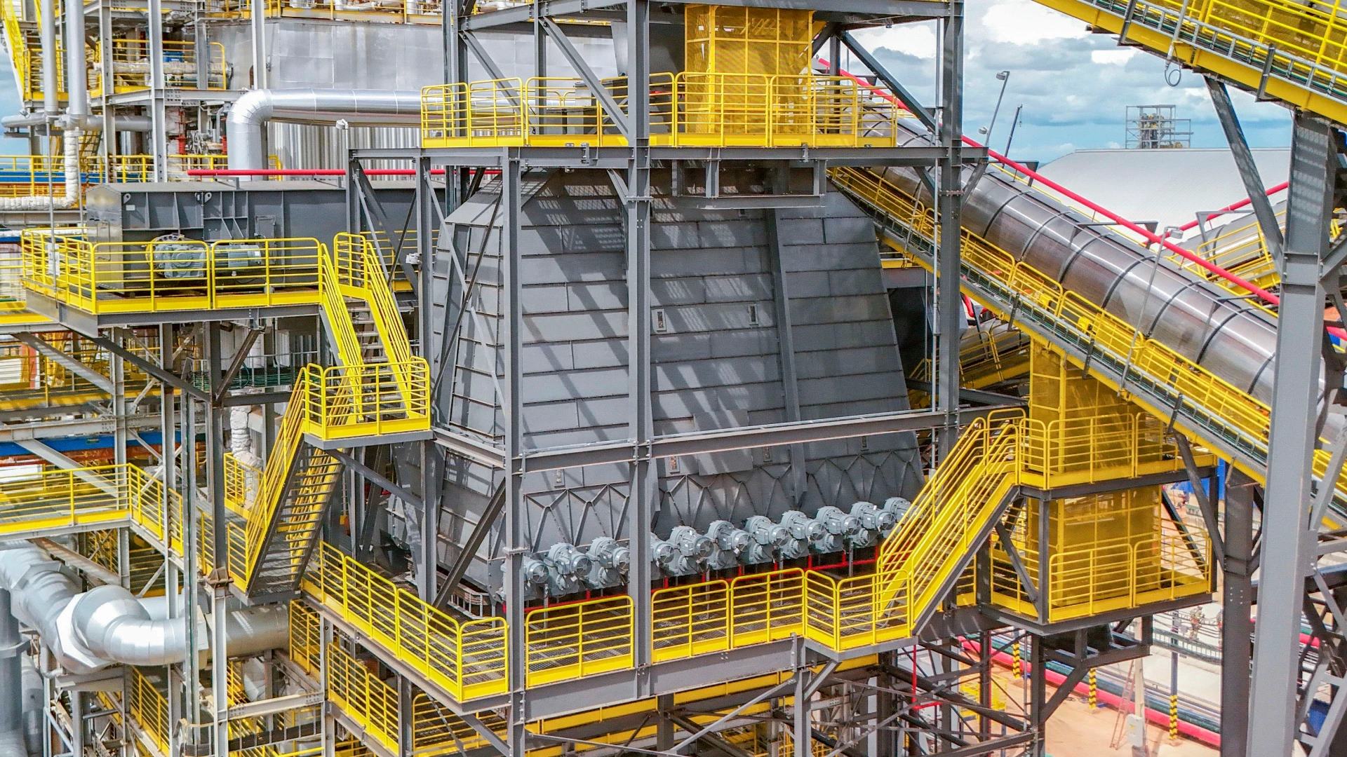
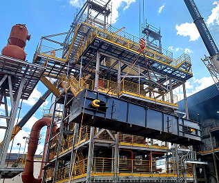
Lung Silo with Screws
Robust equipment with easy access for maintenance, designed for continuous operation and precise dosing.
The lung silos with screws type, both distributor and feeder, are designed for receiving various types of biomass, with the primary function of acting as a buffer, ensuring the regularity of the feed flow to boilers, burners or heaters with nominal load.
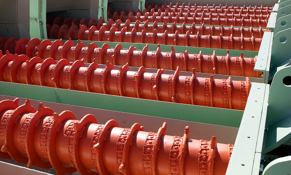
The material is moved by means of helical blades, which allows an uniform and alternating dosage of the fuel to it's destination.
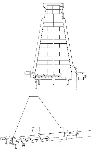
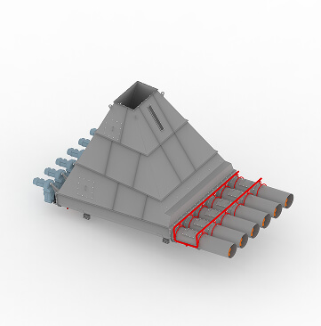
Distributor Lung Silo with Screws
The distributor lung silo with screws is designed to dose and distribute biomass to one or more spots.
It is strategically installed at a spot on the line to provide a buffer and ensure that there is no shortage of biomass in the process.
Depending on the project's requirements, between 2 and 18 screws may be installed with the sizing influenced by several factors, generally associated with the type of biomass (or raw material, in the case of industrial processes) to be conveyed.
In order to increase the lifespan of the equipment, special materials can be used in its construction, such as Hardox or stainless steel screws, or mig welding hardfacing overlays on the surfaces of the screws that come into contact with the biomass.
Technical specifications
| Models | CDD/300 | CDD/400 | CDD/500 | CDD/600 | CDD/700 | CDD/800 |
|---|---|---|---|---|---|---|
| Storage (m³) | 2 to 40 | 2 to 80 | 5 to 150 | 5 to 250 | 10 to 350 | 10 to 450 |
| Width (mm) | 500 to 1.000 | 1.100 to 2.100 | 3.000 to 5.500 | 3.000 to 6.500 | 4.000 to 5.500 | 4.000 to 6.500 |
| Length (mm) | 1.200 to 3.500 | 1.400 to 4.100 | 2.500 to 8.600 | 2.500 to 9.800 | 3.000 to 10.000 | 3.000 to 12.900 |
| Height (mm) | 1.500 to 2.000 | 2.000 to 2.500 | 2.200 to 5.000 | 2.800 to 8.000 | 3.000 to 12.500 | 3.500 to 14.000 |
| Screw Length (mm) | 3.000 to 12.000 | 3.000 to 12.000 | 3.000 to 12.000 | 3.000 to 12.000 | 3.000 to 12.000 | 3.000 to 12.000 |
| Potência das Roscas (cv) | 3 to 15 | 5 to 30 | 10 to 30 | 10 to 50 | 10 to 50 | 10 to 60 |
| Screw Flow rate (m³/h) | 5 to 100 | 4 to 120 | 10 to 150 | 10 to 300 | 10 to 600 | 10 to 1.000 |
| Weight (kg) | 5.000 | 18.000 | 32.000 | 45.000 | 53.000 | 65.000 |
The equipment can be adjusted according to your project's needs.
Feeder Lung Silo with Screws
The feeder lung silo with screws is designed to dose the biomass and feed other equipment, such as boilers and burners.
Between 2 and 6 screws can be installed with sizing influenced by several factors, generally associated with the type of biomass to be conveyed or the size of the boiler to be fed.
In order to increase the equipement's lifespan, special materials can be used in its construction, such as Hardox or stainless steel screws, or mig welding hardfacing overlays on the surfaces of the screws that come into contact with the biomass.
Technical specifications
| Models | CAD/300 | CAD/400 | CAD/500 |
|---|---|---|---|
| Estocagem (m³) | 2 to 10 | 5 to 15 | 5 to 30 |
| Largura (mm) | 900 to 2.500 | 1.100 to 3.900 | 1.500 to 4.500 |
| Comprimento (mm) | 1.500 to 2.600 | 2.900 to 4.500 | 3.000 to 5.000 |
| Altura (mm) | 1.300 to 3.500 | 1.400 to 4.100 | 1.400 to 4.800 |
| Comprimento das Roscas (mm) | 2.000 to 12.000 | 2.000 to 12.000 | 2.000 to 12.000 |
| Screw Power (HP) | 2 to 5 | 4 to 12,5 | 7,5 to 20 |
| Vazão das Roscas (m³/h) | 2 to 10 | 6 to 40 | 10 to 50 |
| Peso (kg) | 3.700 | 9.200 | 12.000 |
The equipment can be adjusted according to your project's needs.
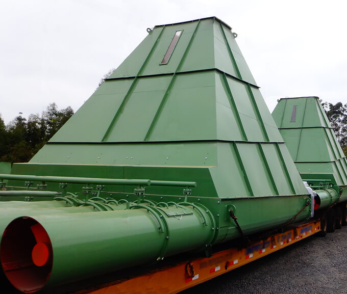
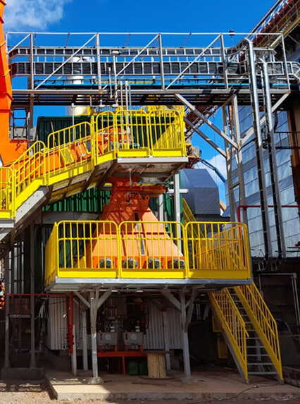
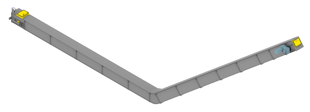
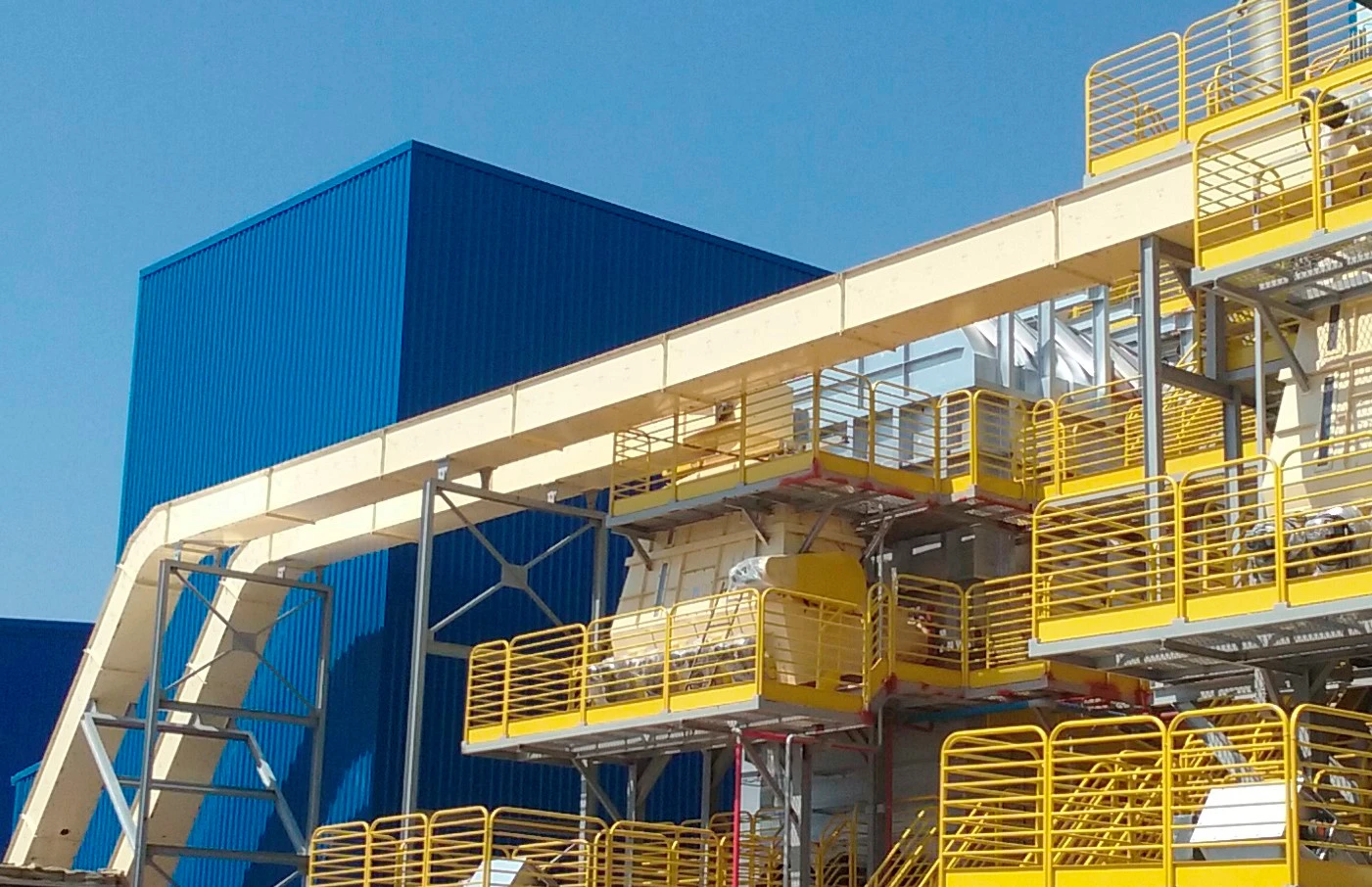
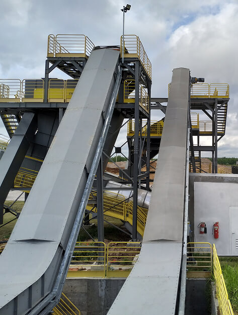
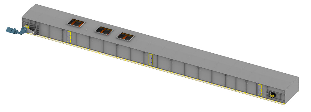
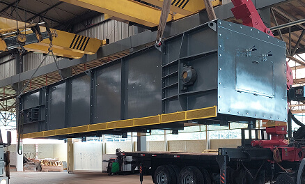
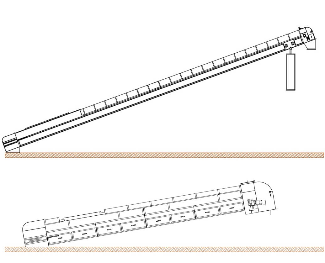
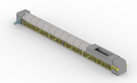
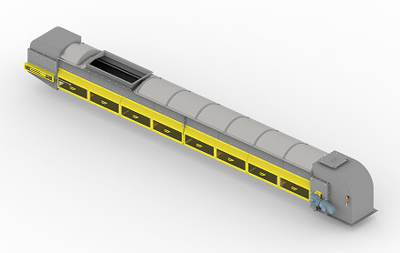
Redler Drag Conveyor
Robust equipment with easy access for maintenance, designed for continuous operation and precise dosing.
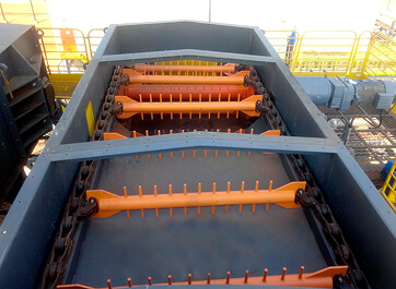
The Redler drag conveyor is an equipment developed for conveying various types of biomass. The movement is performed by slats moving over a flat metal base, either continuously or intermittently, using two conveying chain lines.
Depending on project requirements, roller chains or special forged chains may be installed for this application.
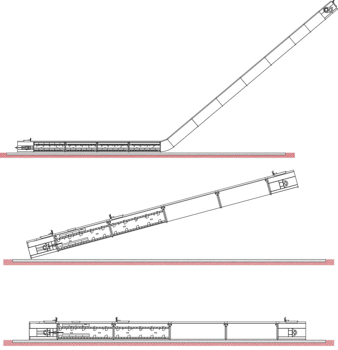
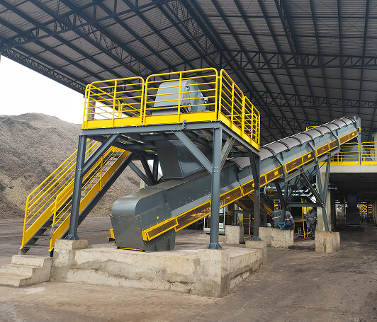
Redler Drag Conveyor for Biomass
It is designed to transport biomass such as wood chips, shavings, sawdust, among others.
Its major advantage is layout optimization, being widely used in compact projects due to its ability to handle steeper slopes during operation.
Technical specifications
| Models | TARD/400 and 500 | TARD/600 and 800 | TARD/1000 and 1200 |
|---|---|---|---|
| Width of the slats (mm) | 400 or 500 | 600 or 800 | 1.000 or 1.200 |
| Width (mm) | 790 to 890 | 1.060 to 1.260 | 1.460 to 1.660 |
| Length (mm) | 14.000 to 50.000 | 14.000 to 50.000 | 14.000 to 50.000 |
| Height (mm) | 650 to 950 | 650 to 950 | 650 to 950 |
| Power (HP) | 7,5 to 40 | 15 to 50 | 25 to 75 |
| Flow rate (m³/h) | 5 to 80 | 100 to 180 | 125 to 200 |
| Weight per meter (kg) | 340 | 450 | 1.100 |
The equipment can be adjusted according to your project's needs.
Redler Drag Conveyor Distributor Type
It is designed to convey biomass such as wood chips and sugarcane bagasse.
It's used to feed boilers with multiple supply points strategically distributed, and its main feature is the dual bottom, which ensures greater system uniformity and allows the feeding of surplus biomass, forming a closed circuit in the process.
Technical specifications
| Models | TARD/800 and 1000 | TARD/1200 and 1800 | TARD/2000 and 2200 | TARD/2500 and 3000 |
|---|---|---|---|---|
| Width of the slats (mm) | 800 and 1.000 | 1.200 and 1.800 | 2.000 and 2.200 | 2.500 and 3.000 |
| Width (mm) | 1.260 to 1.460 | 1.660 to 2.260 | 2.460 to 2.660 | 2.960 to 3.460 |
| Length (mm) | 10.000 to 60.000 | 10.000 to 60.000 | 10.000 to 60.000 | 10.000 to 60.000 |
| Height (mm) | 1.600 to 2.100 | 1.600 to 2.100 | 1.600 to 2.100 | 1.600 to 2.100 |
| Power (HP) | 10 to 150 | 10 to 150 | 10 to 150 | 10 to 150 |
| Flow rate (m³/h) | 30 to 150 | 150 to 300 | 300 to 600 | 600 to 1.000 |
| Weight per meter (kg) | 1.160 | 1.300 | 1.450 | 1.680 |
The equipment can be adjusted according to your project's needs.
Redler Drag Conveyor for Ash
It is designed to convey ash, wet ash, and silicas.
Its major advantage is layout optimization, being widely used in compact projects due to its ability to handle steeper slopes during operation. We also recommend the use of the Redler without curves, equipped with forged chains to convey the ash.
Technical specifications
| Models | TARD/200 and 300 | TARD/400 and 500 | TARD/600 and 700 |
|---|---|---|---|
| Width of the slats (mm) | 200 or 300 | 400 or 500 | 600 or 700 |
| Width (mm) | 510 to 610 | 710 to 810 | 910 to 1.010 |
| Length (mm) | 12.000 to 35.000 | 12.000 to 35.000 | 12.000 to 35.000 |
| Height (mm) | 440 to 800 | 440 to 800 | 440 to 800 |
| Power (HP) | 2 to 4 | 2 to 6 | 2 to 7,5 |
| Flow rate (m³/h) | 0,5 to 10 | 5 to 20 | 10 to 30 |
| Weight per meter (kg) | 230 | 350 | 450 |
The equipment can be adjusted according to your project's needs.
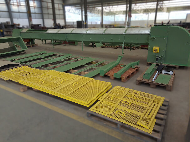
Accessories for Redler Drag Conveyor for Ash

RUD Forky Conveyor Chain
Link dimensions and properties.
Technical specifications
| Description | Breaking Load kN | t | A | B | C | D | E | F | G | Weight / Link kg |
|---|---|---|---|---|---|---|---|---|---|---|
| 102x37x13 Type E | 125 | 102 | 33 | 37 | 13 | 14 | 14 | 38 | 8 | 0,6 |
| 142x50x19 Type E | 220 | 142 | 50 | 55 | 19 | 25 | 20 | 42 | 13 | 1,5 |
| 142x50x19 Type V | 440 | 142 | 50 | 55 | 19 | 25 | 20 | 42 | 13 | 1,5 |
| 142x50x29 Type E | 310 | 142 | 50 | 55 | 2 | 25 | 30 | 62 | 15 | 2,0 |
| 142x50x29 Type E | 620 | 142 | 50 | 55 | 29 | 25 | 30 | 62 | 15 | 2,0 |
The equipment can be adjusted according to your project's needs.
Treatments
Type E - Highly wear-resistant
Surface hardness: 60 – 64 HRC (800 HV)
Hardness layer: 1.5 mm
Type V - High rupture resistance.
Surface hardness: 43 HRC / 440 HV
Below are the advantages of the RUD Forky link.
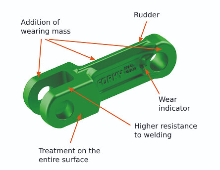
Wear Indication
Easy viewing and assessment of wear on the links.
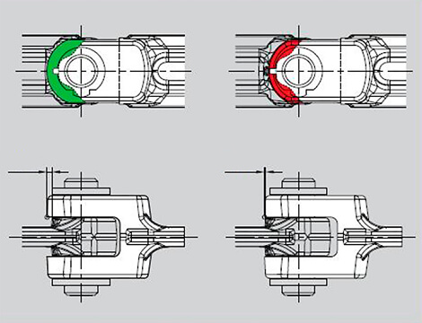
Wear indicator
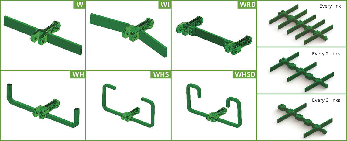
Welded Accessories
Produced according to the technical needs of each application.
Dowel
Produced in high‐alloy steel or stainless steel, heat‐treated with high surface hardness and a deep case‐hardened layer, providing excellent durability.
Hardness:
Alloy steel - 62 - 64 HRC
Stainless steel - 50 - 55 HRC
Dowel CF29
Lock Washer
Its design ensures easy installation and perfect locking of the dowel.
Hardness:
Alloy steel - 62 - 64 HRC
Stainless steel - 50 - 55 HRC

Forky Lock Washer
Cogwheel
Produced with replaceable segments that, after heat treatment, ensure excellent wear resistance and facilitate assembly and maintenance.
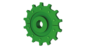
RUD Forky Cogwheel
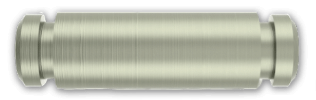
Plain Wheel
Highly resistant, it features a surface with increased hardness for chain contact, providing longer lifespan and low maintenance.
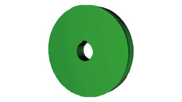
RUD Forky Plain Wheel
RUD Forky Rail
Produced with high manganese content, which brings higher wear resistance and equipment life. It's austenitic properties (non‐magnetic) increases safety in operations.
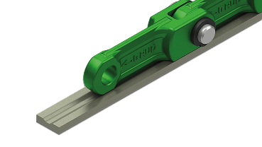
RUD Forky Rail
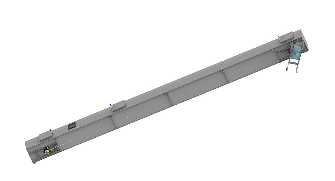
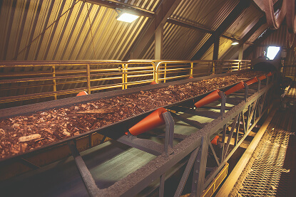
Belt Conveyor
Robust equipment, with easy access for maintenance and continuous operation.
The belt conveyor is an equipment developed for receiving, moving, and dosing various types of biomass, operating continuously or intermittently. The equipment is supplied with dimensions tailored to the project’s needs. Its advantage lies in its modular construction, which makes the convey and assembly simple and practical.
The belt conveyor is equipped with a walkway, guardrail, cover, and side and bottom protections, meeting the requirements of the Brazilian Regulatory Standard NR-12.
Belt Conveyor Truss Type
The movement is carried out via a flat belt (canvas) supported on trapezoidal rollers.
The drive cylinder is rubber-coated with the following specifications: black SBR 60 SHA, with a convex finish and diamond-shaped grooves. The belt tensioning system can be gravity-operated or spindle tensioner type.
Technical specifications
| Models | Width (Inches) | Length (mm) | Power (HP) | Flow rate (m³/h) | Weight per meter (kg) |
|---|---|---|---|---|---|
| TCD/20 | 20" | 10.000 to 60.000 | 3 to 15 | 10 to 60 | 215 |
| TCD/24 | 24" | 10.000 to 70.000 | 5 to 15 | 20 to 100 | 240 |
| TCD/30 | 30" | 10.000 to 135.000 | 10 to 40 | 60 to 200 | 260 |
| TCD/36 | 36" | 10.000 to 145.000 | 12,5 to 60 | 250 to 400 | 320 |
| TCD/42 | 42" | 10.000 to 200.000 | 15 to 100 | 330 to 450 | 370 |
| TCD/48 | 48" | 10.000 to 250.000 | 20 to 100 | 430 to 500 | 420 |
| TCD/54 | 54" | 10.000 to 250.000 | 20 to 100 | 450 to 600 | 490 |
| TCD/60 | 60" | 10.000 to 250.000 | 30 to 125 | 500 to 900 | 540 |
| TCD/72 | 72" | 10.000 to 250.000 | 50 to 150 | 1.000 to 1.600 | 590 |
| TCD/80 | 80" | 10.000 to 250.000 | 60 to 175 | 1.100 to 1.800 | 670 |
| TCD/84 | 84" | 10.000 to 250.000 | 75 to 200 | 1.200 to 2.000 | 730 |
The equipment can be adjusted according to your project's needs.
Belt Conveyor Trough Type
The movement is performed by means of a flat belt (canvas) supported by a trough along the path. Depending on the application and need, the equipment can be supplied with rollers distributed along the trough.
The drive cylinder is rubber-coated with the following specifications: black SBR 60 SHA, with a convex finish and diamond-shaped grooves. It features a spindle tensioner belt system.
Technical specifications
| Models | Width (Inches) | Length (mm) | Power (HP) | Flow rate (m³/h) | Weight per meter (kg) |
|---|---|---|---|---|---|
| TCD/20 (Trough) | 20" | 7.500 to 30.000 | 3 to 10 | 5 to 15 | 175 |
| TCD/24 (Trough) | 24" | 7.500 to 30.000 | 3 to 12,5 | 10 to 20 | 210 |
| TCD/30 (Trough) | 30" | 7.500 to 30:000 | 3 to 15 | 20 to 35 | 240 |
The equipment can be adjusted according to your project's needs.
Components for Belt Conveyors
Scrapers
The main scraper at the drive head is located near the drive drum to clean sawdust/dust from the conveyor belt. This system is comprised of a steel shaft and polyurethane blades. Its adjustment is made by a spring, which keeps the blade pressed against the belt, thus providing more efficient cleaning.

The return scraper is a V-type and is located near the driven drum, on the return side of the belt conveyor. It is mounted in an articulated manner, facilitating self-adjustment, and its function is to eliminate any wood chip/biomass residues that eventually got stuck to the return side.

Rollers
Located at the top and bottom of the belt conveyor, the rollers are meant to support the conveyor belt as well as the load it carries. The guiding rollers are mounted vertically and are meant to guide and align the belt. The rollers are mounted using flanges on pressed carbon steel plates. The sealing consists of a closed block with a double labyrinth seal system, filled with grease and an isolation retainer, recommended for harsh environments with high dust and water exposure.


Magnetic Separators
There are two types of magnetic separators that can be installed on Dujua belt conveyors: The suspended drawer-type magnetic separator is designed to remove impurities and ferrous parts from materials transported on the conveyor belt. A magnetic plate is suspended by cables or chains above the belt, where the materials pass. This plate is positioned at an appropriate distance to attract ferromagnetic items, separating these contaminants from the rest of the raw material. Its cleaning system is manual, simple, and efficient.


The automatic Overbelt or Overband magnetic separator is designed to remove impurities and ferrous parts from materials transported on the conveyor belt. It attracts ferrous particles, which are automatically diverted from the biomass flow. It is ideal for industrial processes that require high iron removal in large volumes of material, operating continuously 24 hours a day. This high-capacity ferrous decontamination system is optimized for use in automated lines, minimizing downtime for cleaning.


Single Seal Side Rubber
The side sealing rubber of the belt conveyor is installed along the inner side of the equipment, according to the project’s needs. It's meant to keep the material on the belt after passing by the receiving trough until the material reaches the speed of the receiving belt. In some cases, the seal covers the entire length of the conveyor to prevent dust dispersion. In addition to increasing productivity by reducing wasted spilled biomass, the sealing rubber also helps minimizing equipment wear.

Double Seal Side Rubber
This type of side seal provides double sealing efficiency using a single strip that adapts to any trough angle, preventing leaks of dust and fine materials. The double seal uses a patented design with an elastomer strip that doubles its lifespan. Dujua also supplies a quick-release clamp option.

Impact Table (Trough between Rollers)
The impact table of the trough‐between‐rollers type is installed where the biomass is received, in order to absorb the impact and prevent damage to the conveyor belt.

Special Impact Table
The special impact table is installed below the belt’s loading zone to absorb the impact of falling material, thus protecting the structure and the belt from damage. In addition to preserving it's integrity, the impact table also helps keeping the belt’s trajectory stable, preventing misalignments and material leakage.

Aluminum-Zinc Metal Cover
The closing cover is coated with an aluminum-zinc alloy applied by hot-dip galvanizing process in a continuous line. This coating layer combines the corrosion resistance of aluminum with the galvanic protection of zinc. It can be supplied in the natural color of the sheet (aluzinc) or pre-painted, according to customer preferences.


Translucent Cover with Quick Coupling
The cover is manufactured with a translucent engineering polymer, with stainless steel fastening claws and a flameproof and impact-proof closing plate. It does not rust, dent, or warp, eliminating the need for painting and maintenance. Its modular components are easily replaceable in case of damage. Compared to metallic covers, it offers superior durability and facilitates maintenance with quick disassembly. It has independent openings on both sides and does not accumulate material on its surface. The translucent characteristic allows light to pass through, enabling the inspection of long sections by opening just one hatch.


Integrating Scale
The integrating electronic scale for weighing on conveyors is known for its high precision and durability, both mechanical and electronic. In addition to weighing accurately, it also measures the instantaneous flow of material on the belt. This helps controlling truck loading, prevents overloading of other equipment in the operation line, and allows precise production control, ensuring a transparent and safe process.


Biomass Measurement System
The biomass measurement system is installed on the belt conveyor to efficiently manage variables that affect combustion in industrial boilers. It uses advanced online systems to measure weight, volume, and moisture, allowing to assess the quality of the biomass and control of the boiler’s energy efficiency. In addition to advanced technology for boilers, the biomass measurement system adds value to the management of sustainable processes, and efficacy of any industry or industrial process.

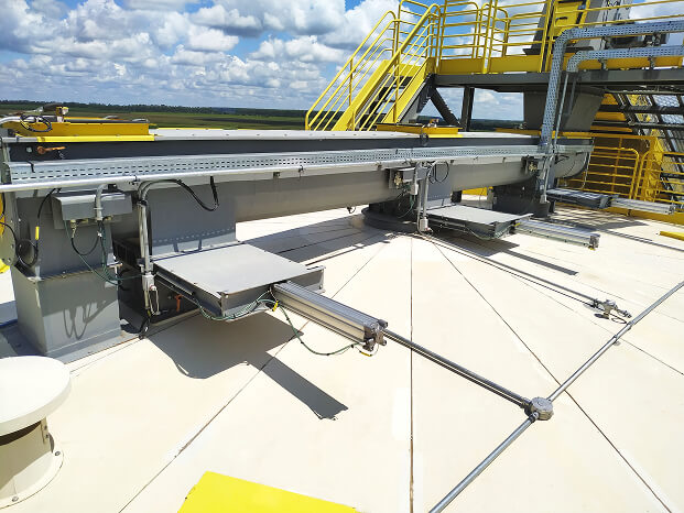
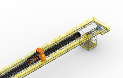
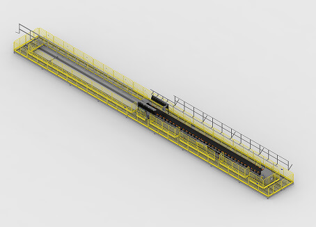
Belt Conveyor Tripper
Robust equipment with easy access for maintenance, designed for continuous operation and precise dosing.
The belt conveyor tripper is an equipment developed for receiving, moving, and dosing various types of biomass, either continuously or intermittently. The equipment is supplied with dimensions tailored to the project’s needs, and its uniqueness lies in its modular construction, which makes transportation and assembly simple and practical.
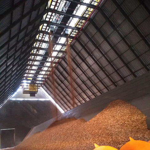
Equipped with walkways and guardrails, in accordance with Brazilian Regulatory Standard NR-12, this equipment is installed in horizontal silos and features a mobile carriage system for the uniform distribution of solid fuel/biomass.
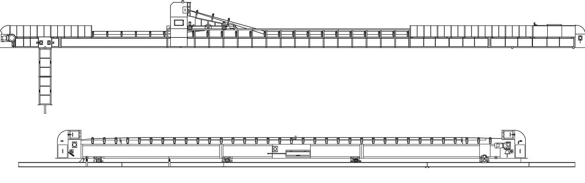
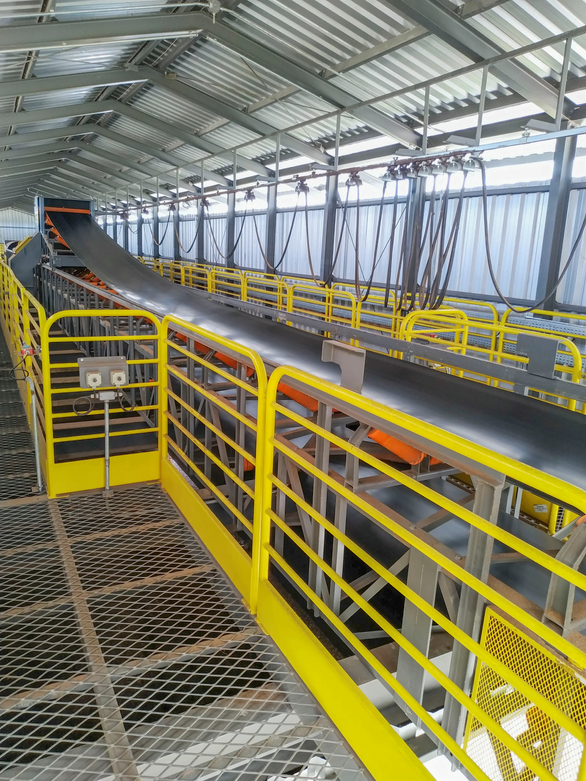
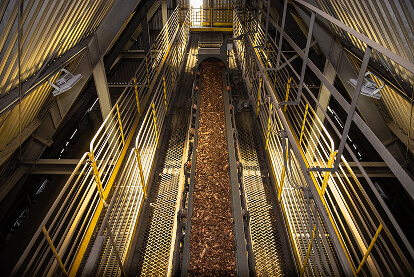
Belt Conveyor Tripper with Carriage System
The movement is carried out by means of a flat belt (canvas) supported on trapezoidal rollers.
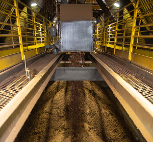
The carriage system type tripper is installed on rails, allowing fuel discharge at any point along the belt conveyor through its V-shaped distribution duct. The carriage moves from one side of the equipment to the other, distributing biomass uniformly.
The drive cylinder is rubber-coated with the following specifications: black SBR 60 SHA, with a convex finish and diamond-shaped grooves. The belt tensioning system can be automatic by gravity or by a tensioner spindle.
Technical specifications
| Models | Width (Inches) | Length (mm) | Power (HP) | Car Power (HP) | Flow rate (m³/h) | Weight per meter (kg) |
|---|---|---|---|---|---|---|
| TTD/SC-24 | 24" | 29.000 to 60.000 | 7,5 to 12,5 | 1,0 | 20 to 100 | 750 |
| TTD/SC-30 | 30" | 29.000 to 135.000 | 10 to 30 | 1,0 to 1,5 | 60 to 200 | 800 |
| TTD/SC-36 | 36" | 29.000 to 135.000 | 12,5 to 50 | 1,0 to 2,0 | 250 to 400 | 860 |
| TTD/SC-42 | 42" | 29.000 to 160.000 | 40 to 75 | 1,5 to 2,0 | 330 to 450 | 940 |
| TTD/SC-48 | 48" | 29.000 to 160.000 | 40 to 100 | 1,5 to 2,0 | 430 to 500 | 990 |
| TTD/SC-60 | 60" | 29.000 to 173.000 | 100 to 175 | 2,0 (2x) | 500 to 900 | 1.050 |
| TTD/SC-72 | 72" | 29.000 to 173.000 | 125 to 175 | 2,0 (2x) | 1.000 to 1.600 | 1.125 |
| TTD/SC-80 | 80" | 29.000 to 190.000 | 150 to 200 | 2,0 (2x) | 1.100 to 1.800 | 1.205 |
| TTD/SC-84 | 84" | 29.000 to 210.000 | 175 to 225 | 2,0 (2x) | 1.200 to 2.000 | 1.260 |
The equipment can be adjusted according to your project's needs.
Belt Conveyor Tripper with Sliding Set
The movement is performed using a flat belt (canvas) supported on trapezoidal rollers.
The sliding set type tripper is installed on rails. Unlike the carriage system, in this case its the conveyor itself that moves. It covers half the total operating length and is equipped with a reversible system that is activated when the equipment reaches the end, reversing the discharge to the opposite head.
The drive cylinder is rubber-coated with the following specifications: black SBR 60 SHA, with a convex finish and diamond-shaped grooves. The belt tensioning system is the spindle tensioner type.
Technical specifications
| Models | Width (Inches) | Length (mm) | Power (HP) | Car Power (HP) | Flow rate (m³/h) | Weight per meter (kg) |
|---|---|---|---|---|---|---|
| TTD/CD-24 | 24" | 29.000 to 60.000 | 7,5 to 12,5 | 1,0 | 20 to 100 | 400 |
| TTD/CD-30 | 30" | 29.000 to 135.000 | 10 to 30 | 1,0 to 1,5 | 60 to 200 | 450 |
| TTD/CD-36 | 36" | 29.000 to 135.000 | 12,5 to 50 | 1,0 to 2,0 | 250 to 400 | 510 |
| TTD/CD-42 | 42" | 29.000 to 160.000 | 40 to 75 | 1,5 to 2,0 | 330 to 450 | 590 |
| TTD/CD-48 | 48" | 29.000 to 160.000 | 40 to 100 | 1,5 to 2,0 | 430 to 500 | 640 |
| TTD/CD-60 | 60" | 29.000 to 173.000 | 7,5 to 12,5 | 2,0 (2x) | 500 to 900 | 700 |
| TTD/CD-72 | 72" | 29.000 to 173.000 | 10 to 30 | 2,0 (2x) | 1.000 to 1.600 | 775 |
| TTD/CD-80 | 80" | 29.000 to 190.000 | 12,5 to 50 | 2,0 (2x) | 1.100 to 1.800 | 855 |
| TTD/CD-84 | 84" | 29.000 to 210.000 | 40 to 75 | 2,0 (2x) | 1.200 to 2.000 | 910 |
The equipment can be adjusted according to your project's needs.
Components for Belt Conveyors
Scrapers
The main scraper at the drive head is located near the drive drum to clean sawdust/dust from the conveyor belt. This system is comprised of a steel shaft and polyurethane blades. Its adjustment is made by a spring, which keeps the blade pressed against the belt for more efficient cleaning.

The return scraper is a V-type and is located near the driven drum, on the return side of the belt conveyor. It is mounted in an articulated manner, facilitating self-adjustment, and its function is to eliminate any wood chip/biomass residues that eventually got stuck to the return side.

Rollers
Located at the top and bottom of the belt conveyor, the rollers are meant to support the conveyor belt as well as the load it carries. They are mounted using flanges on pressed carbon steel plates, with sealing provided by a closed block featuring a double labyrinth seal system filled with grease and an isolation retainer, ideal for harsh environments with high dust and water exposure.


Impact Table (Trough between Rollers)
The impact table of the trough‐between‐rollers type is installed where the biomass is received, in order to absorb the impact and prevent damage to the conveyor belt.

Special Impact Table
The special impact table is installed below the belt’s loading zone to absorb the impact of falling material, thus protecting the structure and the belt from damage. It also helps maintaining the belt’s trajectory stable, preventing misalignments and material leakage.

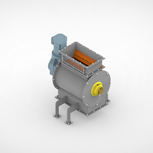
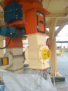
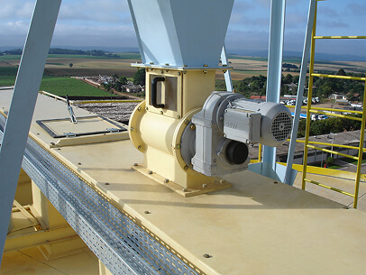
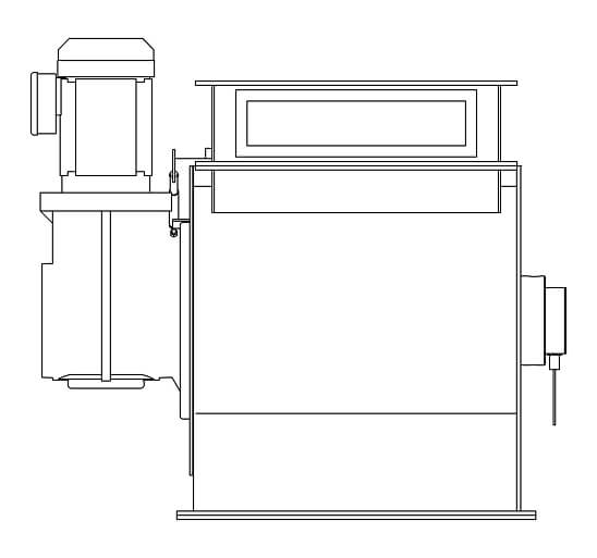
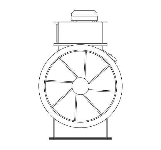
Rotary Valve
Robust equipment with easy access for maintenance, designed for continuous operation and precise dosing.
The rotary valve is an equipment designed for transferring solid fuel or biomass for combustion in boilers, furnaces, or industrial processes.
The operating principle of the rotary valve is based on the use of a rotor. In addition to moving and transferring the material, its function is to dose it precisely, ensuring proper sealing to prevent backflow of fire which is the main technical requirement of this equipment.
Technical specifications
| Models | VRD/10 | VRD/50 |
|---|---|---|
| Diameter (mm) | 300 | 600 |
| Height (mm) | 400 | 1.000 |
| Power (HP) | 1,5 to 3 | 5 to 6 |
| Flow rate (m³/h) | 1 to 10 | 15 to 75 |
| Weight (kg) | 290 | 640 |
The equipment can be adjusted according to your project's needs.